


Please Leave Us A Message
Privacy statement: Your privacy is very important to Us. Our company promises not to disclose your personal information to any external company with out your explicit permission.

 August 25, 2021
Diode and Zener Diode-Based Voltage Divider Circuit Diagrams We may need to obtain several milliamps of current from two or more low-voltage power supplies or voltage sources derived from ordinary DC power supplies, and the power management of such circuits is not Need to be very strict. In these cases, we can use voltage dividers based on diodes, Zener Diodes, and shunt regulators.
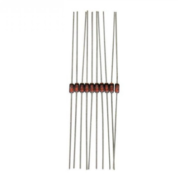
Modern industry offers a wide variety of Zener diodes with power consumption between 0.3W and 1.3W and a reference voltage tolerance of ±2% or better. These Zener diodes can be used to implement certain types of voltage dividers. Figure 2 shows three examples.
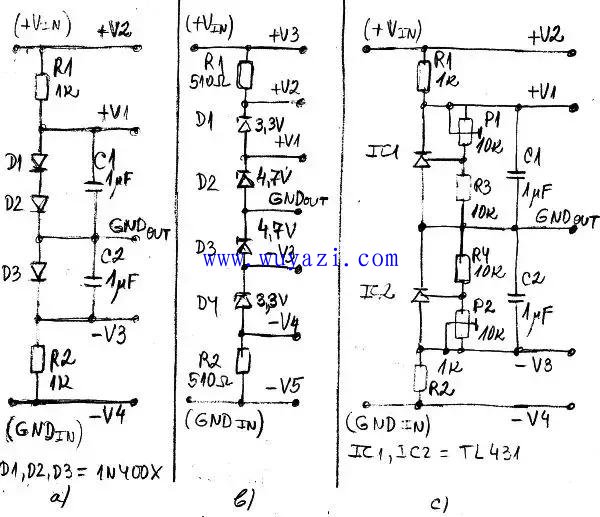
Figure 2: Voltage divider using diodes and Zener diodes. a) a voltage divider using a diode; b) a voltage divider using a Zener diode; c) a voltage divider using two shunt regulators (TL431).
Figure 2a shows a simple voltage divider using a diode. We can connect any suitable number of diodes or light-emitting diodes (LEDs) in series, which will act as shunt or shunt regulators. In this example, two diodes D1 and D2 produce a positive output voltage +V1, and another diode D3 produces a negative output voltage -V3. The output ground GNDout can be at any point between the diodes.
Figure 2b shows a simple voltage divider using a Zener diode. We can connect any suitable number of Zener diodes in series and they will be used as shunt or shunt regulators. In this example, two diodes D1 and D2 produce positive output voltages +V1 and +V2, and the other two diodes D3 and D4 produce negative output voltages -V3 and -V4. The output ground GNDout can be at any point between the Zener diodes. In this example GNDout is between D2 and D3. Zener diodes can be of the same or different types.
Instead of diodes and Zener diodes, we can use a shunt regulator like the TL431. The advantage of this solution is that we can adjust the output voltage by selecting resistors, or trimming potentiometers or other components.
Figure 2c shows a simple voltage divider using a TL431 adjustable shunt regulator. In this example, we use two TL431 or LM341 to generate a positive output voltage +V1 and a negative output voltage -V3. Voltage V1 can be adjusted with trimmer potentiometer P1, and negative output voltage -V3 can be adjusted with P2.
We can connect any suitable number of shunt regulators in series, as shown in Figure 2a and Figure 2b. In fact, these regulators can be seen as adjustable Zener diodes.
The above is the Circuit diagram of voltage divider based on diode and Zener diode we have listed for you. You can submit the following form to obtain more industry information we provide for you.
You can visit our website or contact us, and we will provide the latest consultation and solutions
Send Inquiry
Most Popular
lastest New
Send Inquiry
Tel: 86-0519-18015825110
Mobile Phone: +8618015825110
Email:stella@czcydiodes.com
Website: https://www.changyuanelectronic.com
Privacy statement: Your privacy is very important to Us. Our company promises not to disclose your personal information to any external company with out your explicit permission.
Fill in more information so that we can get in touch with you faster
Privacy statement: Your privacy is very important to Us. Our company promises not to disclose your personal information to any external company with out your explicit permission.